Project Overview
The Morphing Wing project is a senior design project at Florida Institute of Technology. The goal of the project is to create an RC aircraft with a variable wingspan. The variable wingspan will increase the efficiency of the vehicle by allowing the drone to dynamically adjust the wingspan to minimize drag during different parts of the flight profile.
My role in this project is as the Structures Lead, which includes the CAD design, physical prototyping, and manufacturing of the drone. As part of my role, I worked closely with the structures sub-group and the rest of the Morphing Wing team throughout the design and manufacturing of the vehicle.
Although the team designed an entire drone, the extending wing is the focus of the project. The extending wing is the most complex structure of the vehicle. The static wing will need to support regular wing loading, as well as the moving wings’ lift. In addition, the static wing will still need internal space to allow the moving wing to nest inside. The need for a hollow wing with internal features added complexity to the design and manufacturing.
Below is an excerpt from the Morphing Wing Critical Design Review (CDR) document.
Design & Fabrication Approach of the Static Wing
The traditional ways of manufacturing model aircraft wings include cutting out foam; using spars and ribs with a fabric cover; or laying composite on top of a foam or fabric wing. These methods would not allow for the internal cavity required for the dynamic wing to fit inside the static wing. There was also the possibility of making the wing in two parts in a set of female molds and then connecting the wing halves together, but this was deemed to be a more complex and higher-risk approach. To this end, the decision was made to 3D print a male mold out of Polyvinyl Acetate (PVA). This is a water-soluble and 3D printable material often used for support during printing. A composite layup is then done on top of the male mold.
The 3D print was made in sections and stacked together. The sectioning of the wing is necessary due to printing size limitations, but should not affect the strength of the final wing. The sectioning of the print also allows for ribs, stringers, and other required features to be inserted into the male mold prior to the layup. The assembled 3D printed parts and other components are called the mold stack and can be seen in Figure 1.

The mold was 3D printed to allow the composite to take the shape of the required airfoil, while still having the capacity to hold the retracted moving wing. Once the composite has cured and hardened, the PVA 3D print is removed. Because PVA is water soluble, it is easy to remove using warm water without causing any safety concerns. A lightweight 3D printing material that would not be removed was also investigated but this was found to add unnecessary mass to the vehicle.
After the PVA mold is dissolved, the wing is left with the composite skin, as well as the non-dissolvable components that were put into the mold stack. These components are held in place by the epoxy used in the composite layup process, as well as by thin stringers. The components that were in the mold stack included 3D-printed ribs, bearing surfaces, and stringers. A section of the rib and stringer layout can be seen in Figure 2.

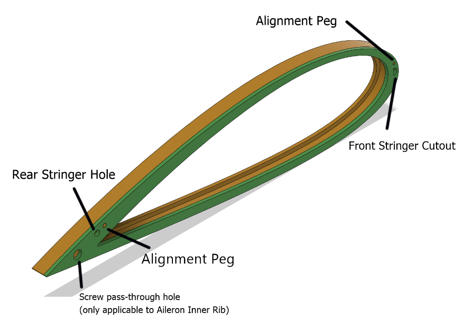
The 3D-printed ribs are made from Polyethylene terephthalate glycol (PETG) and are used both for structural reinforcement and to hold the bearing pads in place. The ribs consist of two parts, the main rib, and a ‘cap.’ The ribs were split for two reasons: to prevent overhangs while printing, and to keep material options available for the bearing pads. As an additional feature, this method also allows a more rigid material to be used as the rib cap in case the planned materials are insufficiently stiff. The rib and rib cap are glued together before the mold stack is assembled, and in order to make sure that they are placed properly an alignment peg was added. There is also a screw pass-through hole which is only applicable on the rib that supports the aileron but is included on all rib caps to simplify the Bill of Materials (BOM). The rib and rib cap can be seen below in Figure 3 with the rib cap in green.
The ribs along the aileron have a different appearance on the trailing edge due to a cutout to allow the aileron. These ribs have all of the same features and functions but are called ‘aileron ribs’ to denote the cutout on the trailing edge.

There are two stringers on the static wing, one on the leading edge and one on the trailing edge. The leading edge has very little space, so a special carbon fiber stringer must be used for this stringer. This carbon fiber stringer can be purchased commercially as a half-round, but costs significantly more than other options. The rear stringer has more space available to it and so uses a fiberglass rod that is cheaper, but larger than the carbon fiber.
The bearing pads provide the surface that the moving wing slides on and are a critical component to the proper functioning of the system. Due to the importance of these components, careful consideration was made to ensure that contingencies would be available. There are two main plans for the bearing pads, a felt-like material, and a slippery plastic. Each material has advantages and disadvantages, but the felt-like material is plan A. The felt is much more forgiving of misalignment and less likely to bind. The downside of this material is that the felt risks bottoming out and having the wing resting on hard surfaces. The slippery plastic would have the opposite risks, with no risk of bottoming out but being more susceptible to misalignment and manufacturing defects. These two options can be easily changed up until the very moment that the composite is applied. After that, they can still be changed but the difficulty increases due to having to reach through the wing to access the more remote bearing pads. An image of the rib and bearing pad assembly can be seen below in Figure 5.

The aileron is 3D printed in multiple sections out of PETG. It hinges between a partially threaded stud on one side and a screw on the other side. The aileron is actuated by using a servo motor mounted on the wing’s upper surface. The servo is connected to the aileron using commercially purchased pushrods. The pushrod connects to a mount on the aileron. Pictures of the aileron and servo can be seen in Figures 6 and 7, and a video of the aileron functioning can be found directly after in Figure 8.


DESIGN AND FABRICATION APPROACH OF THE MOVING WING
The moving skin requires a cutout in order to house the threaded rod used in the extension mechanism, and hard skin to ride on. In order to meet these two requirements the same fabrication process is used for the moving wing as with the static wing. A male mold of the wing is 3D printed in sections out of PVA with 3D printed PETG ribs interspersed. The moving wing mold stack is held together using fiberglass stringers like that used for the rear stringer on the static wing. The moving wing also features attachment points at the wingtip to allow additional components to be mounted as needed. These attachment points can be used to mount a winglet or to secure skids if the wing is hitting the ground during flight operations. An image of the moving wing mold stack can be seen in Figure 9.

WING EXTENSION MECHANISM
The extension mechanism of the dynamic wing is composed of two lead screws within the left and right sides of the static wing. These lead screws push or pull a nut at the end of the dynamic wing, enabling linear movement. The dynamic wing is constrained from twisting by the bearing pads and therefore has to move in and out when the leadscrew turns. Both of the lead screws are mounted to the same central shaft through semi-flexible couplings. These couplings allow for slight errors in manufacturing and assembly, as well as preventing binding or breaking should the wing flex during flight. With both lead screws sharing the same shaft, if there is a failure in the mechanism the wings should remain symmetrical, preventing rapid mid-air disassembly. The shaft is driven by a 90-degree miter gear connected to a stepper motor. The extension mechanism can be seen in Figure 10, where the yellow components are PETG mounting brackets.

The plan for the development of the wing is to start with off-the-shelf components and then shift to lighter-weight custom components as needed. An example of this plan is the lead screws. The lead screws selected for the initial prototype will be a common steel square thread. After the system has been tested, the steel lead screw will be replaced with a more expensive aluminum lead screw. This is also true of fasteners used in the vehicle. An M4 x 8mm screw was selected because it is commonly available in steel but can also be obtained made from nylon. This will reduce the cost of development as well as simplify the variables present during initial testing.
FUSELAGE
The fuselage is made using the same manufacturing techniques as the wing. A male mold is 3D printed out of PVA, with bulkheads interspersed between sections. A composite is then applied to the outside of the fuselage mold stack. The fuselage tapers down into a thin tail boom in order to reduce unnecessary mass. The electronics are housed within the fuselage on an adjustable tray. The adjustment is helpful in order to change the center of gravity during testing. To access the inside of the vehicle, the nosecone of the fuselage is removed with three screws. Images of the fuselage can be seen below in Figures 11 and 12.


The electronics will be placed in the fuselage on top of the electronics tray. This tray can be slid in and out of the vehicle for easy service, and its placement is adjustable in order to control the center of gravity. The tray is prevented from rotation in three axes as well as translation in two axes by slots in the bulkheads and held in place in the remaining translational axis by a screw along the front. There are multiple holes for this screw to allow the tray to shift the center of gravity with repeatable positioning.


ALTERNATIVES CONSIDERED
Many alternatives were considered in the design of the extension mechanism. Early in the design phase, mechanisms investigated included inflating wings, pneumatic and hydraulic pistons, and flexible skins. These methods were not pursued due to a mixture of manufacturing difficulties and mass considerations. In larger vehicles, mechanisms like hydraulic and pneumatic pistons may be practical, but within the planned size for our vehicle adding a pump, compressor, or reservoir to power these devices is prohibitive.
The primary alternative design utilized an extension mechanism meant to provide structural support to the wing. This mechanism was designed to hold onto the dynamic wing and support the wing loading independently from the stationary wing. This alternative extension mechanism rode on three aluminum rods and used three carbon fiber rods for supporting the dynamic wing. This method was developed in CAD software and then simulated under expected loads. The results of the simulation showed that the mechanism as designed would break immediately and catastrophically. In order to strengthen the design to a functional level, a thicker wing chord or a heavier material would be required. Either of these two changes was deemed unacceptable, and so another method for extending the wing was identified. The new method for extending the wing is the current design described earlier.

The manufacturing of the wing was a major concern in the design process. The problem was that with traditional model aircraft-sized vehicles, the wings are either solid foam or have solid ribs that take up a large portion of the inside. With the need for a hollow load-bearing wing, it was decided that a composite skin would be needed. This meant that there needed to be a way to shape the composite to the proper airfoil without a solid foam core. The first idea was utilizing a traditional mold, but such a mold had several problems. One of the main problems with using a traditional mold for the composite was the requirement for the wing to be made in separate pieces. This would be needed in order to free the dried composite from the mold. The two wing components would then have to be bonded together and internal fittings added. There are several places where things can go wrong in this method, especially when thinking about the considerable size of the mold.
The next idea was to shape a male mold out of foam and dissolve the mold using gasoline or acetone. This method had significant problems due to safety considerations such as waste disposal and inhaling of fumes. The solution was to shift to a 3D-printed male mold and then lay the composite on top of the print, permanently embedding the print. Provided that the material was light, the weight may be negligible. This method was pursued for a while until it was realized that a dissolving filament could be utilized instead. Some common 3D printing filaments can be dissolved in water, without any safety or disposal concerns. This was compared to the lightweight embedded print and was found to save approximately 750 grams in the static and moving wings.
ANIMATION
Part of the Senior Design project includes presenting the project as part of the team. Due to the structure of the presentation, the description of the vehicle needed to be as close to three minutes as possible. In order to remain within the allotted time, while still providing a complete understanding of the vehicle, I decided to create an animation of the vehicle that I could display during the presentation. The raw animation was created in Fusion 360, and the text and editing were done in Blender. There is no sound in the video because in the presentation I was explaining the functions of different parts as the video progressed. The animated video can be seen below in Figure
